SPIRIT REMOTE
SPIRIT: Professional System with Robotic Integrations for Television Instrumentation
Presentation
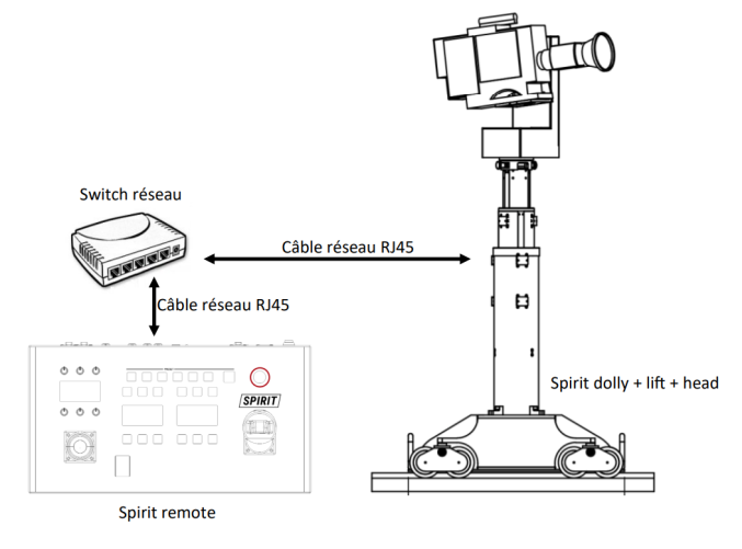
The SPIRIT REMOTE is a control desk used to control multiCAM/polyscope robots. This panel is used in several contexts: For the direct control of one or more robots with or without panbar and for the control of robots via PILOT. Below is an example of a direct control implementation:
If the spirit remote is so versatile in its uses, it is because it is fully configurable. Among other things, each of its functions can be assigned to any
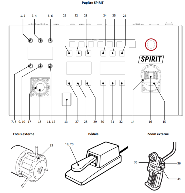
button/encoders. The following diagram details the buttons/encoders on the console.
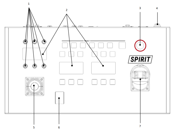
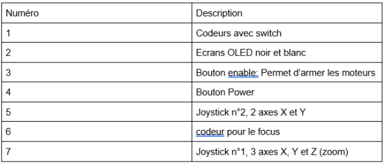
The diagram below is an enlargement of a screen and the buttons around it:
Getting started
Connections
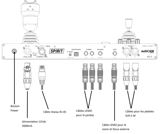
To operate the console you must connect at least the power supply and the RJ45 network cable. The desk is PoE (Power over Ethernet) compatible, with a compatible switch it is possible to power the desk directly via the ethernet cable (see details in technical specifications). The possible connections are detailed below.
Ignition
The console is switched on via the power button (see diagram above).
IP Recovery
To access the web interface, you must first retrieve the console's IP. There are several ways to do this
When the engine starts
When starting up the console, its IP is displayed on the left screen for a few seconds.
Via the INFO button
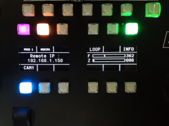
By pressing the INFO button successively, you scroll through various information on the central screen. The information that interests us is “Remote IP:” followed by the IP of the console. The photo below shows what you should see. Here the INFO button is the green button.
If by pressing the INFO button nothing happens, check the connection of the network cable. If this does not solve the problem or the INFO function is not assigned to any key use the following method
RMIP
Use the RM-IP software presented in appendix 1.
Boot with IP reset
This method consists of temporarily changing the console's IP to that entered under the reset button (192.168.1.100). By connecting to a browser at this IP, you can then recover the initial IP or even change it. On the diagram below we see the reset button with the reset IP listed below.
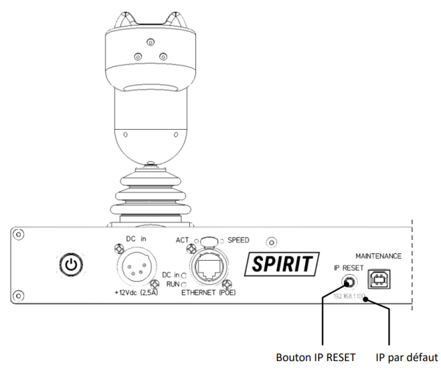
To start the reset, turn off the console then restart it while pressing the IP RESET button. After 3 seconds, release the reset button. You can then connect to the IP listed under the button.
Access the interface
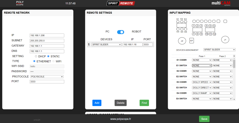
Once the IP has been retrieved to access the web interface, all you have to do is use a web browser like Chrome, Firefox or Edge and enter the IP in url as in the screenshot below:
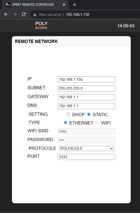
You can modify each field shown in the screenshot above to adapt the desk to your network.
Add a multiCAM PILOT
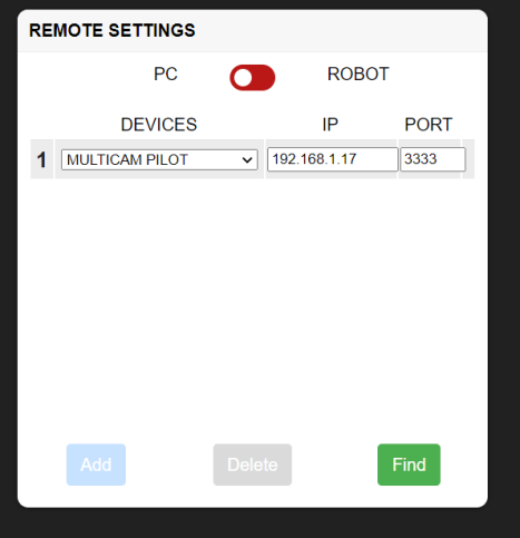
If you are using a PILOT solution to control your robots, click on the PC <> ROBOT switch (see the screenshot below) and enter the IP of the multiCAM PILOT PC. All the configuration and key assignment part will then be useless because it will be done directly via the PILOT interface.
Add bots
To add the robots present on the ethernet network in the SPIRIT Remote, you must first know their IP and locate them. To do this, there are several methods, the first using the RMIP software is presented in Appendix 1. The second is to use the “find” button circled in the figure below
A dialog page should then appear as below:
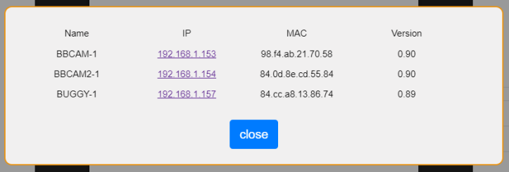
In our example we see that we have 2 spirit heads (bbcam) and a spirit dolly (buggy) on the network as well as their respective IPs. Note the IPs thus obtained for the rest.
Then select your robotic solution from those proposed as in the following screenshot
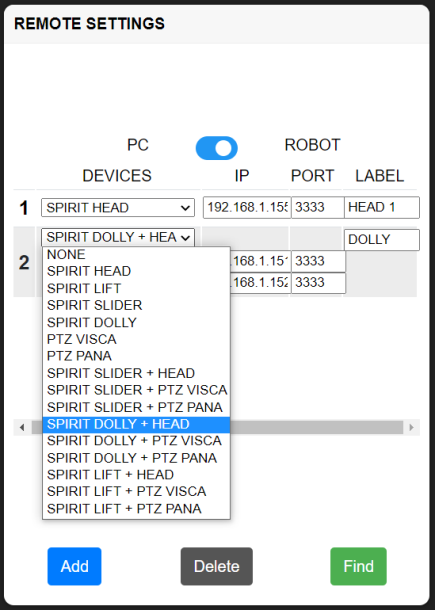
You can interface several robotic solutions on the same SPIRIT remote station. To add another solution click on “Add” (cf. screenshot above)
it is only possible to control one robotic solution at a time with the console. This is why it is necessary to take the robotized solution encompassing the real configuration as much as possible.
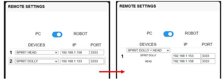
For example, in the screenshot above, we prefer the solution on the right because it allows you to control the dolly and the head simultaneously unlike the solution on the left.
Once you have selected the appropriate solution, enter the IPs of your robots. The default port is 3333, it can be configured via the web page of each machine.
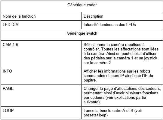
You can also change the name of your solution in “label” to find it more easily. The given name will be written on the screen above the corresponding camera button (see Key assignment > description of functions > Generic > CAM 1-6)
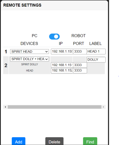
Once all the IPs are entered you should have a page similar to the screenshot above. You can remove a robotic solution with the “delete” button.
To safeguard
Once you have finalized your configuration, save it with the save button at the bottom of the page (see screenshot below). Configuration changes are only taken into account after the backup.
Key assignment
Description of assignable functions
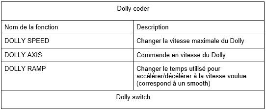
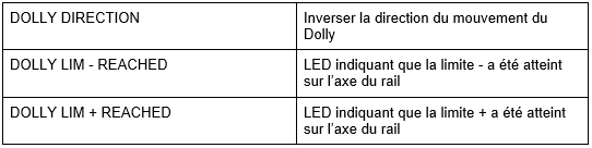
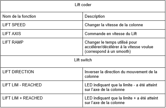
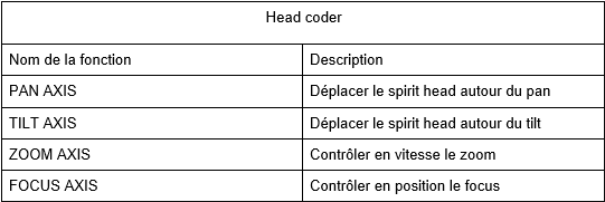
The functions can only be assigned to compatible buttons. They fall into two categories: encoders and switches. The tables below summarize all the assignable functions for each type of robot:
Dolly / Slider
Lift
head
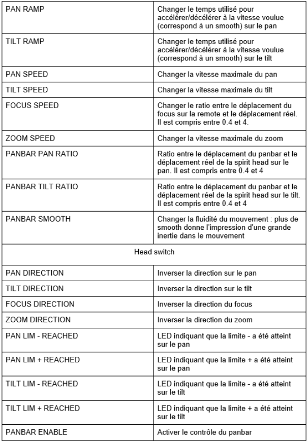
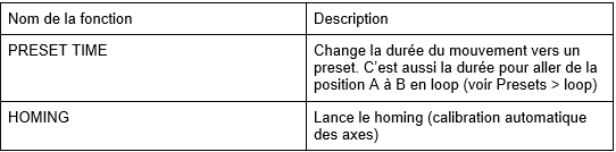
Miscellaneous (present in each type of robot)
Generic
Key assignment
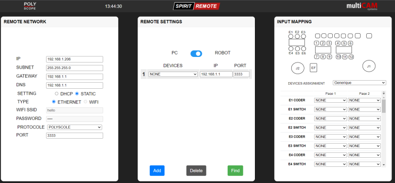
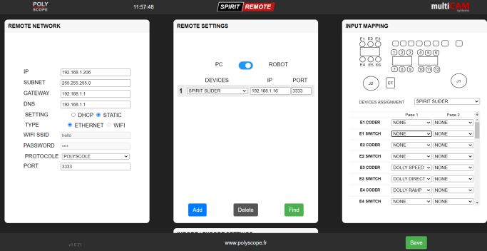
The assignment of the keys is done in the “INPUT MAPPING” part of the web interface presented in the following figure:
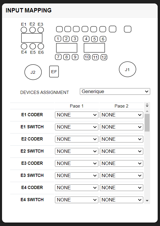
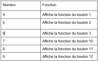
This interface includes a diagram representing a top view of the console with numbered buttons. A DEVICES ASSIGNMENT drop-down list allows you to make assignments for each robotic solution present on your network. And finally a list of each button with the associated function is at the bottom.
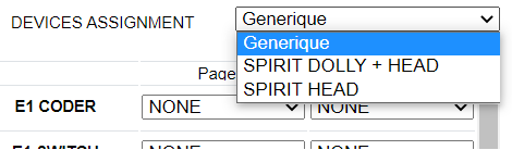
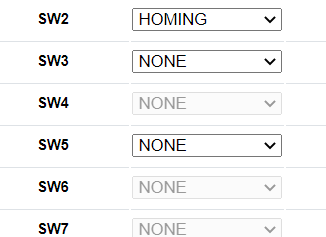
In DEVICES ASSIGNMENT you can choose between “Generic” and your robotic solutions. “Generic” is used to assign functions not linked to a type of machine presented in the previous section, such as the INFO function. The assignment of these keys takes priority over other device assignments. So adding a generic function will gray out the key in the other assignment devices:
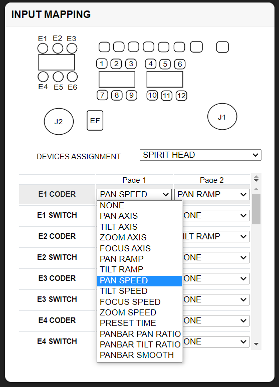
To assign a key click on the associated drop-down list. The name of each button is marked on the left. It corresponds to the name noted on the diagram above. Note that potentiometers E1 to E6 have encoder and switch functions. That is, they are turnable and clickable. The click is associated with the switch. By default, it is used to change the direction of the axis.
It is possible to assign several functions to a button, in page 1 and page 2 (underlined in red in the screenshot above). The PAGE function (assignable in generic) is used to switch from the page 1 function to the page 2 function.
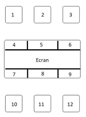
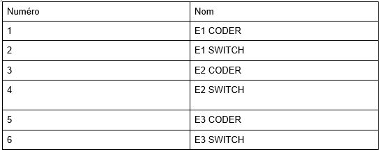
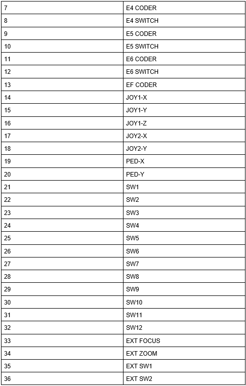
The following diagram details the position of each input:
Once your changes are complete, save them with the Save button at the bottom right
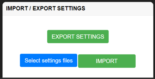
To download the current configuration click on “EXPORT SETTINGS”. To import your configuration to the console, click on “select settings files”, choose your .json file then click on import. The console should then restart with the desired configuration
Presets
The presets are memories in which it is possible to save the current position of the robots. Thus by pressing a preset key, the robot returns to a previously saved position.
The console has keys reserved exclusively for presets.
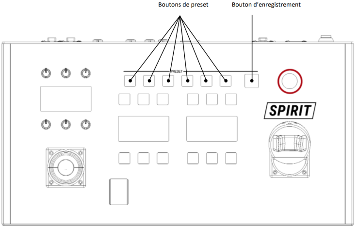
Add preset
To add a preset, position the robots in the desired position then click on the save button (see diagram above). Then click on one of the preset buttons. The preset is then saved in the selected button. You can use up to 6 presets simultaneously.
Preset recall
To return the robot to the saved position, click again on the chosen preset button.
Loop
In addition to the 6 preset buttons, it is possible to record a loop that alternates between 2 positions in a given time (adjustable with the preset time Assignments > description > Miscellaneous > preset time function). To assign the first position press the record button (see diagram above) then the loop button (assignable, see Assignments > description > generic > loop). On the central screen is displayed “loop pos A recorded”. Move to the second position and press loop again. The message “loop pos B recorded” then appears. The loop is now saved. To launch it, simply press the loop button.
Import/export configuration
You can save the current console configuration to a file (export). Caution, this file corresponds to the configuration saved in the console. That is to say that modifications not saved via the save button will not be taken into account even if they are displayed on the web page.
Saving the configuration is done via the IMPORT/EXPORT SETTINGS tab of the web page (see screenshot below). If you don't see this tab, be sure to scroll down the page (the display may hide the tab depending on the screen resolution).
Classic use
In this part we will detail how to start and use a robot via the console.
Start a bot
The start of the robot depends on the configuration, here we will detail the case where the most manipulation is necessary. However, it is possible that neither of the two steps presented below is necessary.
To start a robot there are 2 steps: arm the motors and launch a “homing”. The “homing” is a calibration of the robot allowing it to know its limit positions. To arm the motors, press the enable button (at the top right of the console, see presentation diagram).
To launch the homing, press the homing button, it can be assigned so its position depends on the configuration you have set up (see Assignment > Description > Miscellaneous > Homing). After pressing the homing button your robot starts to move. If not, refer to the robot's web page.
Change speed settings
Changing the speed and acceleration settings is done via the encoders around the left display. You can make speed and acceleration settings for each motorized axis by turning the encoders. It is possible that the number of encoders is less than the number of parameters. To overcome this problem, a PAGE button switches the encoders from their function page 1 to function page 2 (See Assignment > Assignment of keys).
admin
It is possible to access an admin page to update the console and modify the parameters of the joysticks. To access it, enter the ip address of the console in the browser followed by /admin for example: 192.168.1.100/admin
The interface is made up of 4 tabs (DEBUG, ADMIN SETTINGS, PANBAR SETTINGS, FIRMWARE UPDATE) which are detailed in the following pages.
Debug
the debug tab allows the display of information on the state of the console, and is mainly used to identify any bugs.
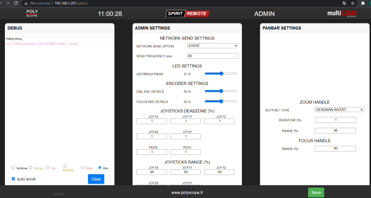
Admin settings
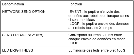
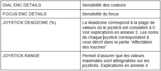
The tab includes several options detailed in the following table:
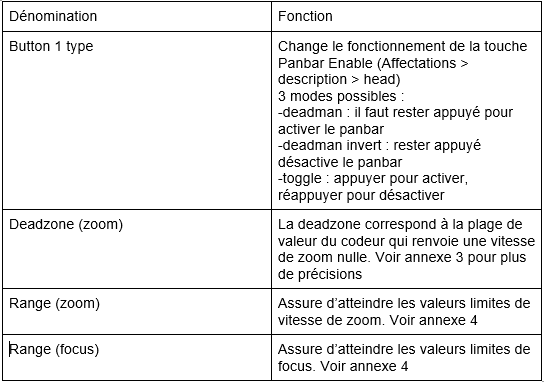
panbar parameters
They are separated into 2 categories “Zoom handle” and “Focus handle”. These parameters are applied to the handles of the panbar respectively the zoom handle and the focus handle. These are the external zooms and focuses shown in Key assignments. The table below describes the function of each option.
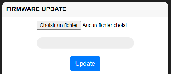
Update
The console update is done via the FIRMWARE UPDATE tab. If you don't see it, be careful to go down to the bottom of the page where it can be hidden depending on your screen definition.
The update can include 2 files: a firmware file (always present) and a spiff file. To perform the update correctly, you must update with the firmware file, then update again with the spiff file. the file names look like: Remote_1_x_xx_firmware.bin
Remote_1_x_xx_spiffs.bin
To start the update with a file click on “choose a file” then select your firmware file and press “Update”. Once the desk has restarted, repeat the same operation with the spiff file.
Attention, the spiff is a memory file for the firmware. When updated, the current configuration file is overwritten. The console will therefore restart with its factory configuration, with a different IP (192.168.1.100 or 192.168.1.152). To avoid losing your configuration remember to save it before (see importing exporting a config). You must also provide a network compatible with the gateway 192.168.1
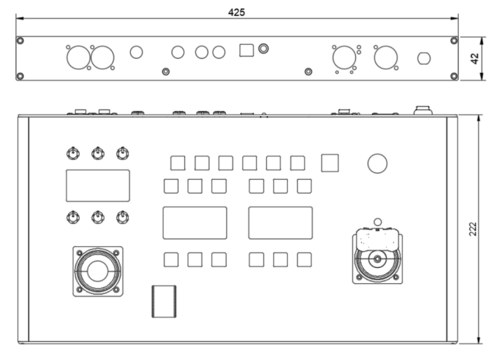
Technical specifications
Dimensions
Connectivity
Here are the different communication standards used by the console:
Ethernet: 10/100Mbps Cat 5
Wi-Fi: 802.11b/g/n
The console can also be powered via Ethernet with POE (Power over Ethernet)
The standard used is: IEEE 802.3at & IEEE802.3af
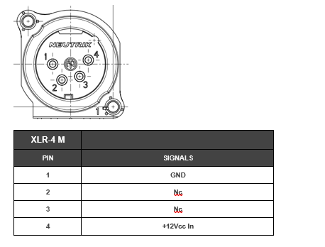
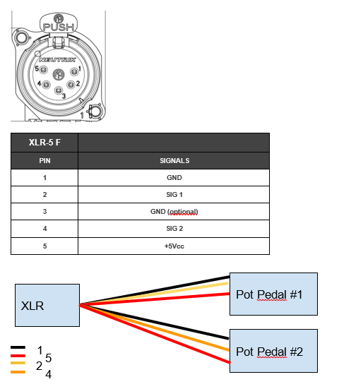
Pinout
This part summarizes the connections of the various connectors on the console.
Power supply +12Vdc
XLR-4 Male
Panbar Pan / Tilt
Tracking
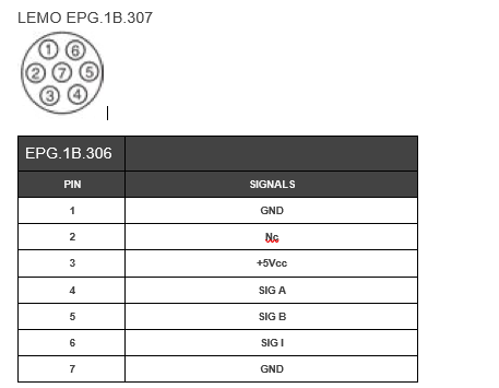
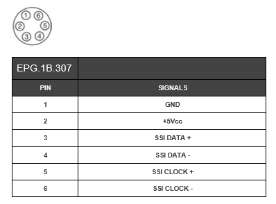
LEMO EPG.1B.306
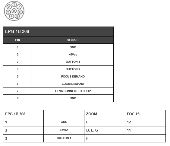
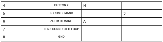
Lens (Optical)
LEMO EPG.1B.308
Pairs of pedals (1 and 2)
XLR-5 Male
Appendices
Annex 1: RM-IP
On the supplied computer / multicam you can find a software named RM-IPSetupTool, if it is not available, you can download it for free from Sony's website. All recent polyscope devices are compatible with this software which allows them to be identified. Once RM-IP is launched, you will come across the following interface:
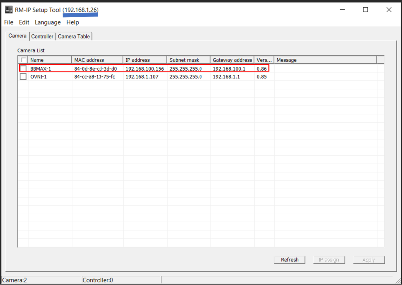
On each line, the information of interest to us is the robot's name and IP address. The computer's IP is also given (underlined in blue). We can see here that our IP (192.168.1.26) is not on the same subnet as the bbmax-1 (babycam maxi) which is at 192.168.100.156. This is problematic because it prevents communication. The method to solve this problem is detailed in appendix 2.
Appendix 2: network config
It is possible that the network is linked to the local network of the studio, in particular to set up the freeD (protocol for augmented reality). It is therefore conceivable that all the IPs are not available and even that the range of IPs used is different. In this part we will therefore focus on how to re-configure each device to give it an adequate IP.
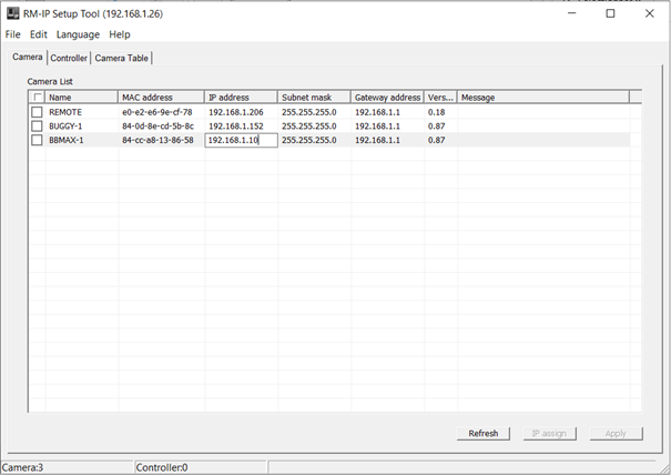
Change IPs from RM-IP
RM-IP allows you to directly modify the IP of a device, just click on the IP to modify and change the field as presented below. Once the field has been modified, all you have to do is click on "Apply" to change the IP.
Change IPs from web interfaces
It is also possible to modify the IP via the console's web interface. To do so, go to the REMOTE NETWORK section then modify the values of IP, SUBNET and GATEWAY.

Change the IP of the PC under Windows
If the PC cannot access the console's web page, it may be that its IP is not in the correct range. We will detail here how to modify the IP of a PC under Windows.
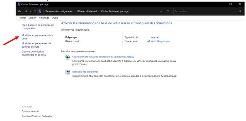
Go to Control Panel > Network and Internet > Network and Sharing Center, then Change adapter settings.
Right click on Ethernet and go to properties
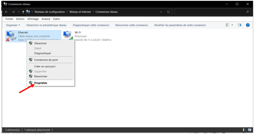
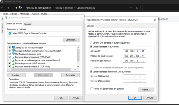
In the properties double-click on “Internet Protocol version 4 (TCP/IPv4)”.
The window that opens, allows you to modify your IP as well as the mask and the gateway. The gateway to put is your IP by replacing the last number with 1. For example, if the IP you enter is 192.168.100.26, the gateway will be 192.168.100.1 . The subnet mask is rarely to be modified, it must be left at 255.255.255.0 . Once the changes have been made, press OK.
change pc ip in mac os
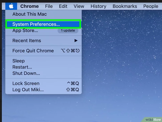
Taken from wikihow.com
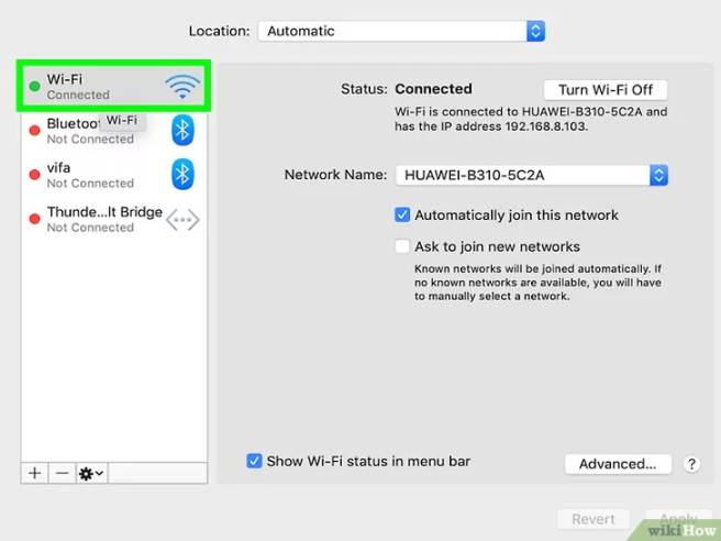
Go to System Preferences
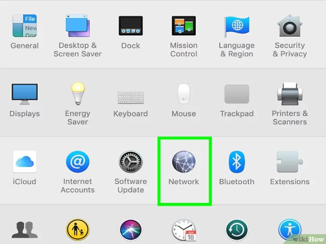
Then click on network:
Then select the network you use and on which the robots are located:
Then click on Advanced at the bottom right of the window. Go to the “TCP/IP” tab and choose Manual from the Configure IPV4 drop-down menu:
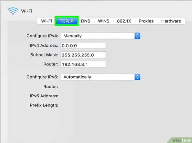
You can now enter the desired ip. Make sure to enter an address in the same subnet as your robots to be able to detect them.
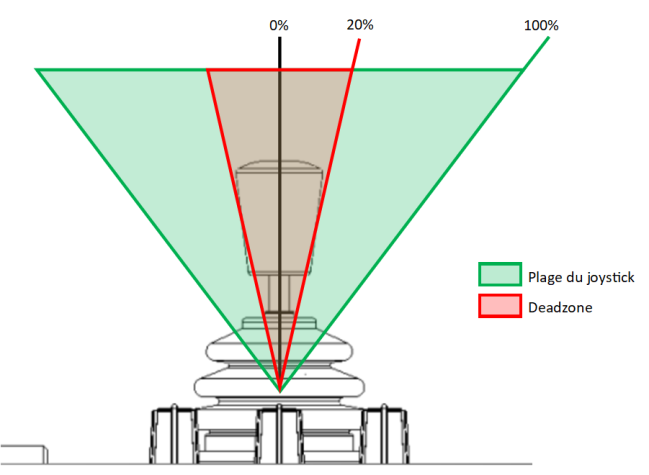
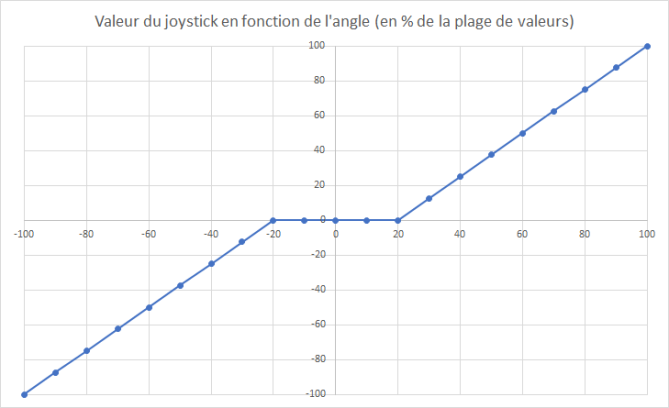
Appendix 3: Deadzone
In the diagram and graph below we see the impact of a 20% deadzone on the values that the joystick can take. The deadzone is used to filter the small values returned by the joystick. This limits measurement noise and potential drift.
Annex 4: Joystick range
The joystick works by returning a voltage between 0 and 5V. But it happens that the maximum achievable value is less than 5V for example. The range of values is therefore configured to be sure of being able to reach the maximum speed values. So for a joystick range of 90%, a value of 4.75V(2.5x0.9+2.5) is enough to return the maximum value of the joystick to the robots.
This option therefore has the main role of ensuring the symmetry of the joysticks. If you see that your robot is going faster at full speed in one direction than in the other, it is probably because the value of joystick range is too high. In the example below we see that with a range at 100% we do not obtain symmetrical output speeds (92% and -100%) because the joystick does not go up to the theoretical 5V. Passing the range to 90% we see that the output speeds will be symmetrical (100% and -100%)

Glossary
Firmware : File containing the microcontroller program.
Spiff : Memory file for firmware.
homing : Calibration of multicam robots allowing the robot to locate itself in relation to its limits.
dead zone: Range of values where the joystick is considered in its neutral position.
Tidy: Allows you to ensure that the limit values of the joysticks are achievable. Detailed explanations in appendix 4
encoder : A rotary encoder or rotary sensor is a type of sensor making it possible to provide angle information, by measuring the rotation carried out around an axis.
Switch : Pushbutton. Not to be confused with the network switch which allows devices to be linked via ethernet.
Preset : Saving the position of the robot. Preset recall is movement to the stored position.